2D thin airfoil theory with unsteady b.c.
The following blog post develops a theory for the lift and moment coefficient of an aerofoil undergoing unsteady motion in a fluid. We will assume that the flow is inviscid and 2D; moreover, we will completely neglect the dynamics of the airflow and hence consider only the unsteadiness in the boundary conditions. The airfoil is considered thin (to be further discussed later) and undergoing small oscillations in a flowing fluid. The term small refers to the magnitude of such oscillations when compared to the magnitude of the mean flow itself. The largest limitation of this theory is that it neglects the dynamics of the air when it reacts to a change in the boundary conditions. Such effect is well captured by more complex unsteady models such as Wagner or Theodorsen. At the conclusion of this article, more space is dedicated to a discussion about what is missing and how the dynamics of the air should be incorporated. On the other hand, the mathematics that we will develop in this blogpost is interesting and rather complex and worthy of presentation. In addition, it can be used as a foundation upon which more complex theories will be developed.
\[\newcommand{\muh}{\hat{\mu}} \newcommand{\summ}[3]{\displaystyle \sum_{#1=#2}^{#3}} \newcommand{\dd}{\text{d}} \newcommand{\qt}{\tilde{q}} \newcommand{\var}{\text{var}} \newcommand{\cov}{\text{cov}} \newcommand{\vh}{\hat{V}}\]
Introduction
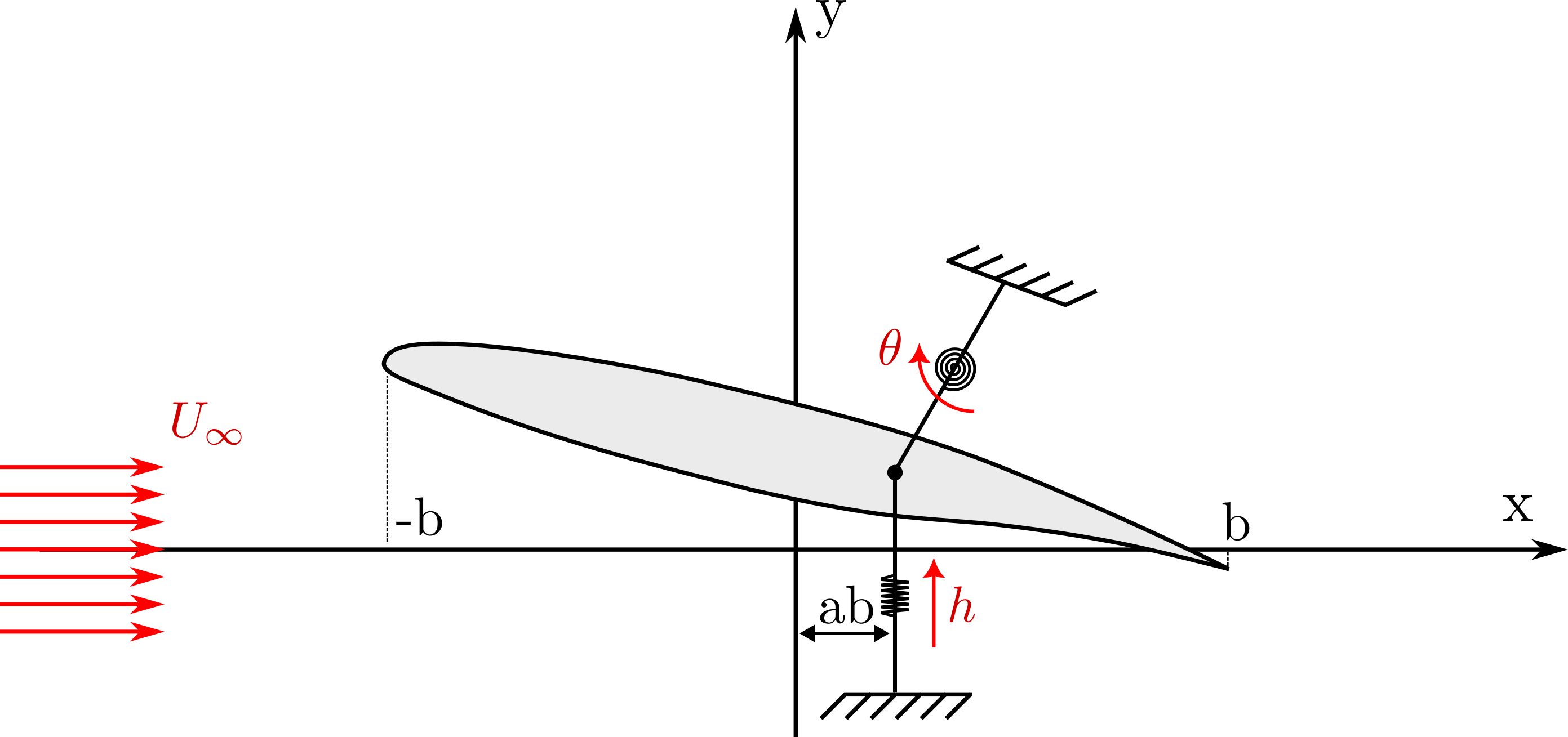
We consider an airfoil that is udergoing a pitching and heaving motion around a particular point, denoted by fulcrum. The setup is conviniently depicted in the following image

The airfoil has a chord of \(2b\) and is immersed in a flow parallel to the x-axis with magnitude \(U_{\infty}\). The motion can be decomposed into a pitching motion, \(\theta\) reprents the angle, and a heaving motion, where \(h\) represents a distance from a fixed point.
Linearized description of the motion
We now ask how we can describe the motion of the airfoil. As commonly done in airfoil theory, we describe the airfoil surface with two curves, the upper one \(y_0^u(x)\) and the lower one \(y_0^l(x)\) (here \(y_0\) refers to the initial condition, i.e. when \(h=0\) and \(\theta=0\)). A point in this surface will move by a certain displacement \(u(x,t)\), which should describe the rotation and displacement around the fulcrum.
\[\begin{equation} y(x,t) = y_0(x,t) + u(x,t) \;. \end{equation}\]If we assume that the displacements are small enough then we can write
\[\begin{equation} u(x,t) = h(t) + (ab-x) \theta(t) \;. \end{equation}\]The key result is that, if we use \(y_0\) as reference surface, the displacement of a point is equivalent to a dispalcement of a flat plate. The displacement in the x direction is negligible.
This is equivalent to a small perturbation in the velocity field of the airfoil
\[\begin{equation} \dot{u}(x,t) = h(t) + (ab-x) \theta(t) \;. \end{equation}\]Linearized boundary conditions
The no-peneratration boundary condition imposes that the normal component of the velocity at the boundary is zero. This means that if we indicate with \(v = (v_x, v_y)\) the velocity of the body, \(w=(w_x,w_y)\) the airflow velocity and \(n\) the normal vector perpendicular to the surface of the airfoil at every point, the no penetration boundary condition reads
\[\begin{equation} n^T \ w = n^T v \; . \end{equation}\]We now take a virtual perturbation around a rest condition i.e. \(w=w_0+ \Delta w\). The new equation reads
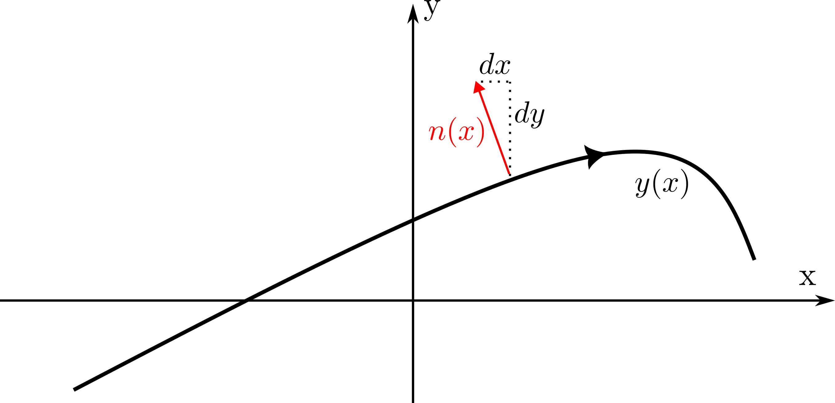
\[\begin{equation} \left. \begin{aligned} &n_0^T w_0 + n_0^T \Delta w + w_0^T\Delta n = n_0^T v_0 + n_0^T \Delta v + v_0^T\Delta n \\ &n_0^T \Delta w + w_0^T\Delta n = n_0^T \Delta v \; . \end{aligned} \right. \end{equation}\]The reader should confirm that the order zero term cancels because when the airfoil is at rest the boundary condition is automatically respected and that \(v_0 = 0\) for definition. This gives the linearized version of the boundary condtion that the airflow should repect. Assuming \(w_0 = (U_{\infty},0)\) the only object that requires care is the normal vector. For a generic function \(y(x)\) a perpendicular outward-pointing vector is \((-y'(x),1)\) (where the negative sign ensures that it points upwards),

The above picture should clarify the setup. In reality this vector needs to be normalized in order to be the normal vector \(n(x) = \frac{(-y'(x),1)}{\sqrt{1+y'(x)^2}}\). Actually this can be reprsented by a vector a divided by its norm \(n_0 = \dfrac{a}{(a^Ta)^{1/2}}\). One should check that
\[\begin{equation} \Delta n = \Delta \dfrac{a}{(a^T a)^{1/2}} = (I - n_0 n_0^T) \dfrac{\Delta a}{(a^T a)^{1/2}} \, \end{equation}\]in this particular case we can say that \(a = (-y'(x),1)\) and hence \(a_0 = (-y_0'(x),1)\) and \(\Delta a = (-u'(x),0)=( \theta(t),0)\). The last result is due to the fact that u is a small displacement around the rest condition and hence can be considered as a perturbation.
The computations yield
\[\begin{equation} n_0^T \Delta w = \dfrac{\dot{h}+(ab-x)\dot{\theta}}{\sqrt{1+{y_0'}^2}}-\dfrac{U_\infty \theta}{(1+{y_0'}^2)^{3/2}}+\dfrac{U_\infty y_0'(x)}{\sqrt{1+{y_0'}^2}} \;. \label{eq:dw_1} \end{equation}\]Now we assume that the airfoil is infinitely thin and that the boundary conditions can be applied to the mean line. We further assume that \(y_{ml}'(x)\approx 0\) so that we can neglect the denominator in Eq.\ref{eq:dw_1}. Assuming that we can rite the perturbation as \(\Delta w = (w_x,w_y=v)\) the product with the normal vector would yield the scalar \(-w_x y_0'+v\) and the first part can be dropped because it is the product of two small quantities.
The final result is reported in the following equation
\[\begin{equation} v^{ml} = \dot{h}+(ab-x)\dot{\theta}-U_\infty (\theta(t)+y'_{ml}(x)) \;. \label{eq:dw_2} \end{equation}\]Eq.\ref{eq:dw_2} reports the y component of the perturbation velocity evaluated at the mean line of the airfoil that enforces the linearized non-penetration boundary condition. This perturbation is generated by the airfoil and its movement in the flow. In the next section we show how we can further simplify this problem using Complex Analysis and potential flows.
Mean Line condition

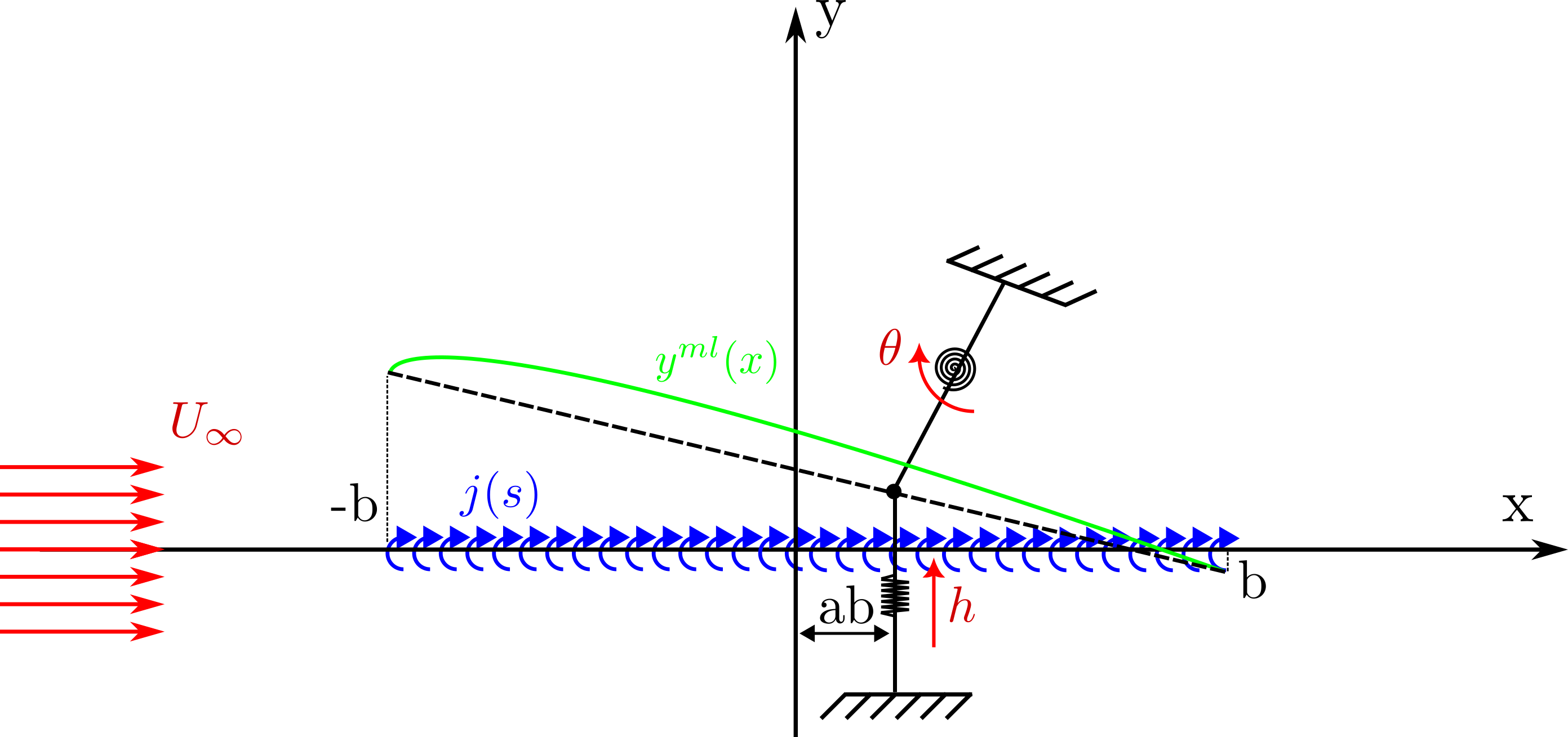
We now assume that the perturbation velocity is induced by a vortex sheet at \(y=0\) of strength \(j(s)\). To further setup the problem we turn to potential flow and complex analysis. The idea is to write the complex velocity field as a complex number \(w=u-iv\) and use simple flows (uniform, source/sink, vortex, …) to build more complex flows. In our case the flow that we will use is the vortex flow
\[\begin{equation} w (z) = \dfrac{\Gamma}{2\pi i} \dfrac{1}{z-s} \;. \end{equation}\]The above formula represents the velocity induced by a line vortex placed at \(z=s\). In our case we have a vortex sheet which can be thought of as a series of infinitesimal vortices with strength \(j(s)\ \dd s\). The induced velocity will be the sum of all the induced velocities
\[\begin{equation} w (z) = \dfrac{1}{2\pi i} \int_{-b}^{b} \dfrac{j(s)}{z-s} \ \dd s\;. \end{equation}\]This formula gives the perturbation velocity induced by the vortex sheet at any point s of the complex plane. The vortex strength is unknown but we want it to be the one that enforces the linearized boundary conditions that we derived before. To further simplify the problem we impose the boundary condition not on the mean line but on the line \(y=0\). We can proceed to evaluate it in the x-axis using Plemelj’s theorem
\[\begin{equation} \dfrac{w(x,y=0^+)+w(x, y=0^-)}{2} = \dfrac{1}{2\pi i} \text{p.v.}\int_{-b}^{b} \dfrac{j(s)}{x-s} \ \dd s = -i v^{ml}\;. \end{equation}\]Where the p.v. symbol indicates that we have to take the principal value of the integral. This leaves us with a integral equation to solve. This is because we know the expression of \(v^{ml}\) (found by linearizing the b.c., see Eq.\ref{eq:dw_2}) but we do not know the expression of \(j(s)\) which appears under the integral sign.
The solution is reported in the following equation
\[\begin{equation} w (z) = U_{\infty} -\dfrac{1}{\pi}\sqrt{\dfrac{b-z}{b+z}} \int_{-b}^{b} \sqrt{\dfrac{b+s}{b-s}} \dfrac{v^{ml}(s)}{z-s} \ \dd s\;. \end{equation}\]This gives the whole perturbation velocity field at any point \(z\) that respects the linearized boundary condition.
Force and moment coefficients
To compute the force coefficients we will have to compute an integral of a function of the complex velocity field. We will do that using Blasius integrals, but before, it is useful to expand the velocity field in a Laurent series, as this will greatly simplfy the computation of the integrals. The two terms that depend on z expand with
\[\begin{equation} \left. \begin{aligned} &\dfrac{1}{z-s} = \dfrac{1}{z}\dfrac{1}{1-z/s} = \dfrac{1}{z} \displaystyle \sum_{n=0}^{+\infty}(\dfrac{s}{z})^n = \dfrac{1}{z}+\dfrac{s}{z^2}+...\\ & \sqrt{\dfrac{b-z}{b+z}} = i\left( 1-\dfrac{b}{z} + ...\right)\; . \end{aligned} \right. \end{equation}\]The Laurent series of the velocity field is therefore
\[\begin{equation} \left. \begin{aligned} w (z) = U_{\infty} & - \dfrac{i}{\pi z} \int_{-b}^{b} \sqrt{\dfrac{b+s}{b-s}} \ v^{ml}(s) \ \dd s\\ & -\dfrac{i}{\pi z^2} \int_{-b}^{b} \sqrt{\dfrac{b+s}{b-s}}\ (b-s)\ v^{ml}(s) \ \dd s \\ & + ... \;, \end{aligned} \right. \end{equation}\]Lift coefficient
To compute the lift coefficient we will use the first Blasius formula which reads
\[\begin{equation} F_x - i F_y = i \dfrac{\rho}{2} \oint_C w^2(z) \dd z \; . \end{equation}\]To compute the integral we will resort to Cauchy’s residue theorem which allows us to compute the integral by a simple evaluation:
\[\begin{equation} \oint_C f(z) \dd z = 2 \pi i \sum \text{res}(f(z))\; . \end{equation}\]This is possible because we have already taken the Laurent series. We should simply evaluate the term in \(w^2\) that contributes to the residual (which is the one that depends on \(z^{-1}\)). The result reads
\[\begin{equation} F_y = -2 \rho U_{\infty} \int_{-b}^{b} \sqrt{\dfrac{b+s}{b-s}} \ v^{ml}(s) \ \dd s \; . \end{equation}\]Now we substitute the definition of \(v^{ml}\) from the boundary conditions (see Eq.\ref{eq:dw_2})
\[\begin{equation} F_y = -2 \rho U_{\infty} \int_{-b}^{b} \sqrt{\dfrac{b+s}{b-s}} \ \left( \dot{h}+(ab-s)\dot{\theta}-U_\infty (\theta(t)+y'_{ml}(x)) \right) \ \dd s \; . \end{equation}\]This integral should be simplified and the result non-dimensionalized by divinding with \(\rho U_{\infty}^2 b\). After all these simplifications we get the following result
\[\begin{equation} C_L = 2 \pi \left( \theta - \dfrac{\dot{h}}{U_\infty} + b \left( \dfrac{1}{2}-a \right)\dfrac{\dot{\theta}}{U_\infty} - \alpha_0 \right) \; . \label{eq:cl} \end{equation}\]Where \(\alpha_0\) is the so-called zero-lift angle of attack and is defined by
\[\begin{equation} \alpha_0 = - \dfrac{2}{\pi b} \int_{-b}^{b} \sqrt{\dfrac{b+s}{b-s}} \ y'_{ml}(s) \ \dd s\; , \end{equation}\]and depends by the curvature of the mean line (for a symmetric airfoil it is zero).
Moment coefficient
The moment coefficient should be computed using, again, Blasius’ formula for the moment which reads
\[\begin{equation} M_0 = -\dfrac{\rho}{2} \text{Re}\left[\oint_C z w^2(z) \dd z \right]\; . \end{equation}\]The computations are very similar to the previous part (evaluate the Laurent series for \(w^2(z) z\) and use Cauchy’s theorem) and, after nondimensionalizing with \(2\rho U_\infty^2 b^2\) the result reads
\[\begin{equation} C_{M0}= \dfrac{\pi}{2} \left( \dfrac{\dot{h}+ab \dot{\theta}}{U_\infty} - \theta + \beta_0 \right)\; . \end{equation}\]The result is, however, usually reported taking the aerodynamic center (quarter chord) as a reference point. This can be achieved using the moment transport theorem which states that,
\[\begin{equation} C_{Mac}= C_{M0} + \dfrac{C_L}{4}\; . \end{equation}\]The final moment coefficient reads
\[\begin{equation} C_{Mac}= -\dfrac{\pi}{4} \left( \dfrac{\dot{\theta}}{U_\infty} +2(\alpha_0 - \beta_0) \right)\; . \label{eq:cm} \end{equation}\]In this formula,
\[\begin{equation} \beta_0 = - \dfrac{2}{\pi b^2} \int_{-b}^{b} \sqrt{(b+s)(b-s)} \ y'_{ml}(s) \ \dd s\; , \end{equation}\]Conclusions
Equations \ref{eq:cl} and \ref{eq:cm} report the lift and moment coefficient for an aerofoil undergoing small oscillatory motion in a mean flow. To compute them we linearized the rather complicated time-dependent boundary condition and generated a potential flow that respects that condition. The largest limitation of this theory is not the linerization itself but rather the fact that we do not consider the dynamics of the air. The perturbation flow is still a potential flow which means that reacts istantaneously to a change of the boundary conditions. This is obviously wrong. But how wrong? The potential flow approximation captures very well the behaviour of the external flow but completely neglects the dynamics of the boundary layer and of the wake. To see how, lets assume that our airfoil is initially not oscillating and, without loss of generality, we assume that it is ymmetric and at zero angle of attack. The airfoil produces no lift and therefore the circulation around it its zero. When the angle of attack is increased the airfoil will start to produce lift (some of that is due to the actual nonzero value of the angle of attack and some to the oscillatory motion \(\dot{\theta}>0\), see Eq. \ref{eq:cl}). This means that the circulation of the airfoil becomes more and more negative. The total circulation must however remain zero. This is no surprise and simply means that some positive circulation is released in the wake. The circulation is not stationary as it moves with the fluid velocity and is therefore transported at \(\infty\) with velocity \(U_\infty\). This process takes time and while the released positive circulation is near the airfoil it will induce some velocity on it thus reducing the effective angle of attack. This means that it takes some time for the airfoil to reach the \(C_L\) value dictated by Eq. \ref{eq:cl} and this is not captured by our model.